How PEC Inspecting Pressure Vessel Insulation Support Rings
Ask an expertThe oil and gas industry requires vessels of various geometries to store liquids and gas at high temperatures and pressure. Their strong steel walls and insulation systems are central elements for a safe and efficient operation, but this combination also sets the table for a self-destructive process: water ingress in the insulation system. Water ingress can cause the vessel’s shell to corrode away, compromising the structural integrity while remaining completely invisible to the naked eye. Pulsed eddy current is a well-established inspection technique that can detect and size steel wall loss under such insulation systems, but it finds a stout challenge in this application. The usual presence of insulation support rings provides a platform where engrossed water tends to accumulate and stagnate, locally accelerating the corrosion progress. Pulsed eddy current can be used to detect this localized corrosion, but it is limited by the interference caused by the insulation support rings. This application note demonstrates what performance can be expected from pulsed eddy current inspection to promote a safer and more economical operation of these critical components.
The Challenge
Assess pressure vessel corrosion in the vicinity of the insulation support ring, which strongly affects pulsed eddy current signals.

Figure 1: Example of Pressure Vessels
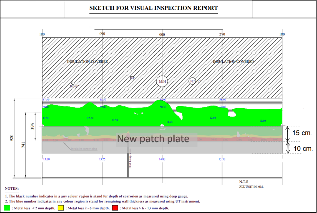
Figure 2: Example of Corrosion Mapping
Pressure vessels are relatively large components used to store liquid and gas at high pressures and are composed of thick wall components ranging between 12.70 to 38.10 millimeters (0.5 to 1.5 inches) in thickness. They are designed and built according to standards such as the ASME Boiler and Pressure Vessel Code (section VIII). Their high-temperature operation condition implies using at least 50.80 millimeters (2 inches) of insulating materials which are held in place with insulation support rings that prevent the insulation from moving and ensure the asset’s safety.
Corrosion under insulation is one of the main corrosion mechanisms in this application. The corrosion, caused by water or condensation that ingresses under the insulation of pressure vessels, is generally found just above the insulation support rings as shown in the ultrasonic technique map in Figure 2. The severity of the corrosion generally increases by getting closer to the ring. Material degradation is a potential threat that must be steadily monitored rigorously to ensure the integrity of the asset and to avoid possible health and environmental issues in the case of a hazardous product leak.
The insulation support ring thickness varies as a function of the operating conditions of the component. Nevertheless, the varying support ring thickness will strongly influence the pulsed eddy current signals within the vicinity which can lead to false-positive indications. Common techniques to appraise corrosion have intrinsic limitations. Most of them require removing the insulation material and generally need surface preparation. It may be dangerous to perform in-service inspection as it would risk disturbing the remaining material and cause a leak.
Evaluating the extent of the corrosion above the insulation support ring requires advanced data analysis tools developed in recent years in combination with a clear understanding of the influence of the insulation support ring on the signals. A major oil and gas company has thus challenged Eddyfi Technologies to assess defects on representative vessel components.
The Solution
An advanced pulsed eddy current solution combined with an optimized analysis and inspection workflow.
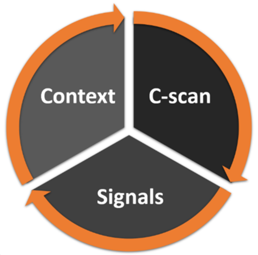
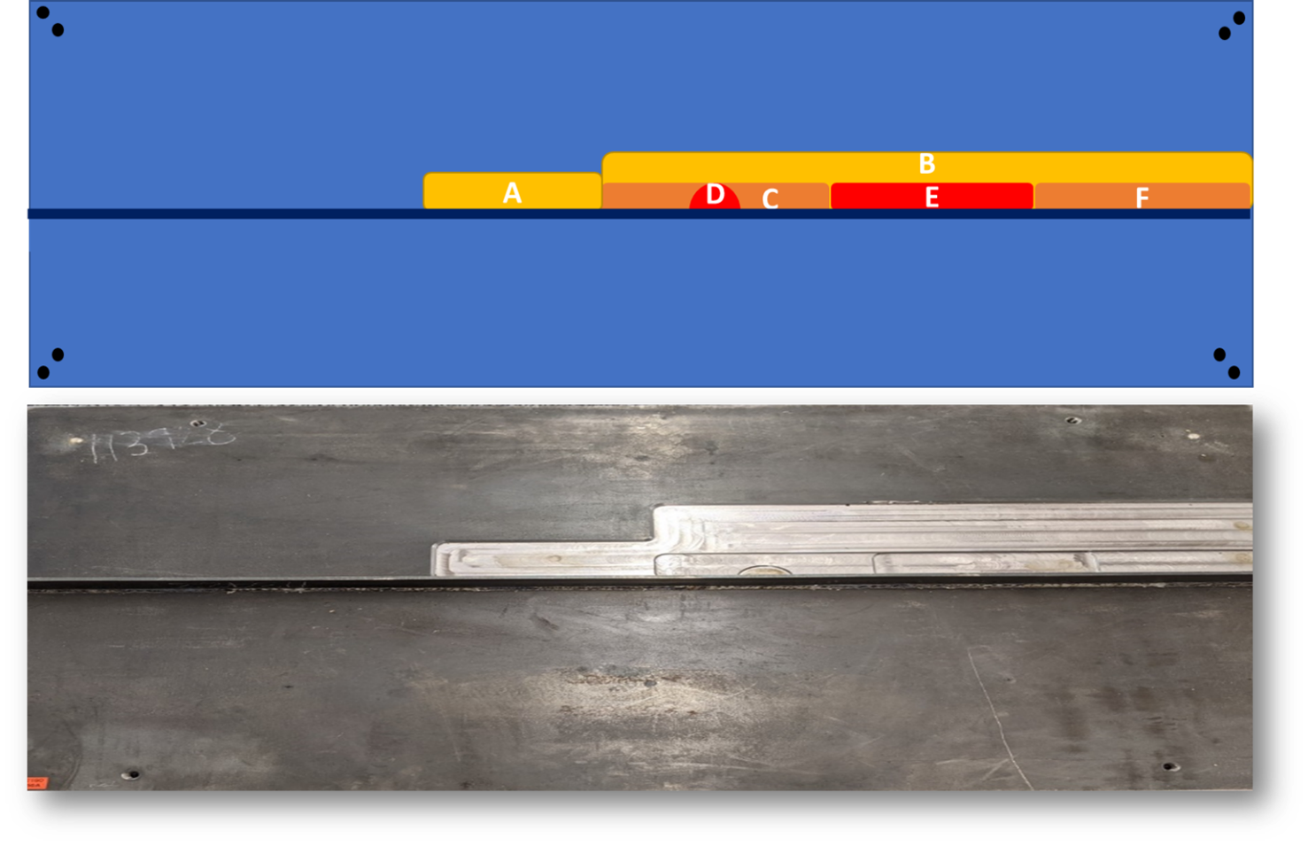
Figure 3: Representative Vessel Component with Defects.
Top: Scheme; Bottom: Photo
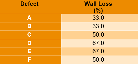
Table 1: Specifications of the Manufactured Defects
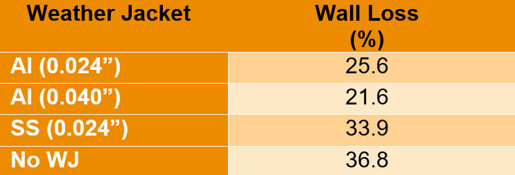
Table 2: Average Wall Thickness (%) in the Defect with the PECA-6CH-MED Probe
The Eddyfi Technologies Lyft® pulsed eddy current solution was specifically designed for evaluating corrosion under insulation on in-service carbon steel components. The technique is now covered by several industry standards, such as ISO 20669, API RP 583, and the ASME section V, article 21. Pulsed eddy current is a versatile inspection technology which provides an average remaining wall thickness through insulation and coatings. Unlike several non-destructive techniques, pulsed eddy current does not require direct access to the surface component, which makes it a technology of choice for inspecting large pipes and vessels. This also implies that no surface preparation is required. The Lyft Pro advanced analysis software also enables the use of an algorithm such as compensated wall thickness, which allows for more accurate sizing of indications that are smaller than the probe’s footprint. The PermTool™ is used to discriminate false-positives from true wall loss indications.
Nevertheless, the inspection of vessel components with pulsed eddy current requires careful consideration of the following three essential aspects:
- 1. Look at the C-scan to find areas of interest while considering the varying baseline and noise level,
- 2. Look at the signals from data points in the areas of interest, and
- 3. Use the context to evaluate its influence on the C-scan and signals to make an informed call.
This challenge was addressed by scanning with the pulsed eddy current array probe PEC-6CH-MED, the representative 25.40-millimeter (1-inch) thick vessel component shown in Figure 3, comprising a wide range of typical defects ranging from 33% to 67% (Table 1).
The plate was scanned at high resolution in dynamic mode to best highlight the effects of the insulation support ring on the defects. The results are presented in the following figures: Figure 4 shows the signals over the insulation support ring and illustrates how the PermTool, an advanced feature of Lyft Pro, clearly identifies the ring as a false-positive indication by having the vector pointed out in the false-positive region. When compared to the signal in Figure 5, the trace of the PermTool signal is enlarged due to the combination of the defect and the false-positive indication signals. Typically, the insulation support ring influences the signals up to one footprint, 78.74 millimeters (3.1 inches) in the present case.
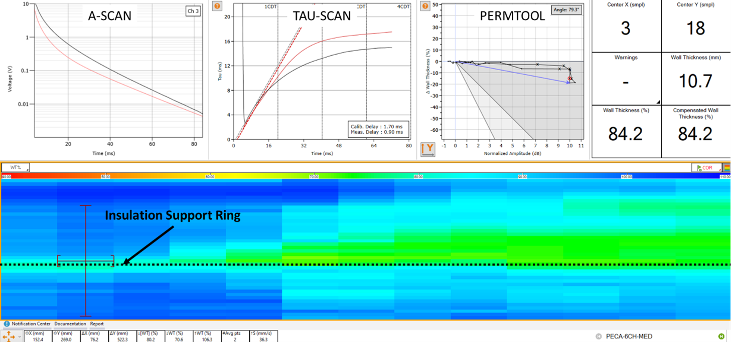
Figure 4: C-Scan Signals of the Insulation Support Ring
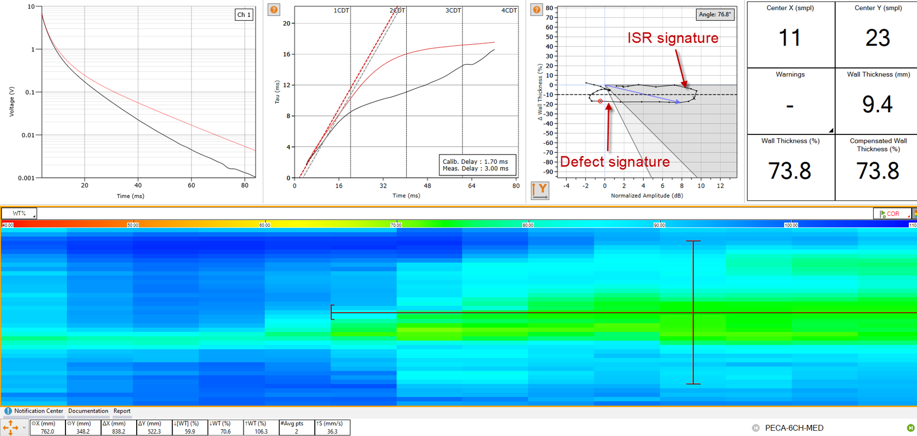
Figure 5: C-Scan Typical Signals of Defects Close to the Insulation Support Ring
Benefits
- Reliable inspection of pressure vessels without expensive removal of insulation system, promotes safer and more economical operations.
The solution’s benefits are undeniable:
• In-service inspection of the asset: The Lyft pulsed eddy current solution does not require shutting down the distribution systems. All inspections can be done on in-service components, leading to significant cost savings.
• No need for time-consuming surface preparation, increasing inspection productivity.
• Pulsed eddy current can detect significant wall thickness variations within one footprint of an insulation support ring that greatly influences the signals.
• Advanced sizing algorithms provide accurate measurements within ±10 percent of the nominal wall thickness and can identify false-positive signatures such as the one of an insulation support ring.
The pulsed eddy current solution can efficiently overcome the challenge of detecting significant corrosion near the insulation support ring found within pressure vessels. All inspections can be performed on in-service systems, requiring no downtime, and allowing for better planification of maintenance operations. Contact us to discuss how to best implement the leading pulsed eddy current inspection solution in your operations today.