Magnetic Flux Leakage (MFL) Tank Inspection
MFL is a simple to use, rapid and robust corrosion detection technique.
Details
The basic structure of an MFL inspection tool is illustrated in Figure 1 and reflects the design of the MFL scanner manufactured by Silverwing. This tool comprises of a magnetic yoke (i) and a set of magnetic sensors arranged as a vector (ii) in order to cover an area in one pass. These components are situated at the bottom of the scanner. Both the yoke and sensor vector travel in tandem across the surface of a steel plate (iii) along the X-axis. The orientation of the magnetic yoke and vector of sensors are 90° to the direction of travel.
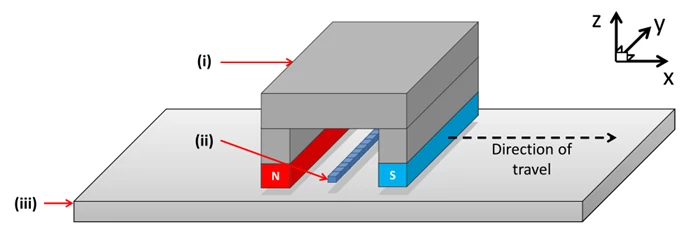 Figure 1: Basic MFL scanner comprising of a magnetic yoke (i) and a vector of magnetic sensors (ii) positioned above a steel plate (iii). Neither (i) or (ii) are in contact with (iii).
For simplicity, a cross-section of the MFL scanner is considered, as illustrated in Figure 2. The MFL signal, coming from this cross-section, is created as the yoke and sensor move along the surface of the plate collecting a series of MFL measurements. The recording of one MFL measurement is as follows.
A magnetic field is induced in a steel plate from the magnetic poles of the yoke (i) and is tuned to a strength where the magnetic flux (ii) saturates a steel plate of uniform thickness (iii). The presence of material loss (simply referred to here as ‘defect’) (iv) produces a magnetic reluctance to the flow of flux causing some to be forced outside the boundary of the plate. Item (v) is the natural path of the leaking flux, the MFL, and occurs both above and below the steel plate.
In the context of tank floors, only one side of the plate is normally accessible and this is from within the tank. Measurements are gathered with suitably placed magnetic sensors (vi), normally located between the poles to measure the MFL. Both the yoke (i) and sensors (vi) then moved a predefined distance to record the next leakage measure.
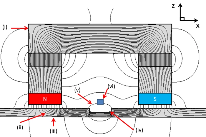
Figure 2:A static cross-section of the MFL scanner from Figure 1 with the induced magnetic field. Again, the magnetic yoke (i) induces a magnetic field (MF) (ii) into the steel plate (iii). In this example, the steel plate contains material loss.
MFL is sometimes combined with another technology as on its own MFL cannot differentiate if the corrosion is topside or bottom side of the tank floor.
STARS (Surface topology air reluctance System)
The STARS technique is a new patented NDT technique that detects the variation of the magnetic flux as it enters the surface of the steel plate. Defects on the top surface of the plate alter the flow of the magnetic flux and this alteration can be detected via STARS.
The STARS approach uses a complementary set of sensors in the air-gap between the pole of the magnetic yoke and the top surface of the steel plate (shown in Figure 6). Basically, as the gap between the surface of the pole and the surface of the plate increase, the magnetic flux density in the gap decreases. Thus, any variation in the top surface of a steel plate, i.e. in the presence of defects, the magnetic flux density in the air-gap changes and these changes are measured and recorded.