Alternating Current Field Measurement (ACFM®)
Detection and Sizing of Surface Cracks in Metals Through Coatings
Details
Alternating current field measurement (ACFM) is an electromagnetic inspection technique that introduces an alternating current into the surface of a component to detect surface-breaking cracks.
The presence of a crack disturbs the electromagnetic field and the return signal is instantaneously converted by advanced mathematical techniques so that operators are alerted to the presence of defects.
Immediate defect sizing and recording is a major benefit compared to other NDT methods. Results from independent testing shows ACFM matches magnetic particle inspection (MPI) performances when inspecting underwater structural welds. The amount of missed and spurious signals is significantly lower with ACFM compared to MPI and conventional eddy current testing (ECT).
With ACFM’s lower cleaning requirements and fewer false calls, inspections are significantly shorter, saving customers money.
Ask an Expert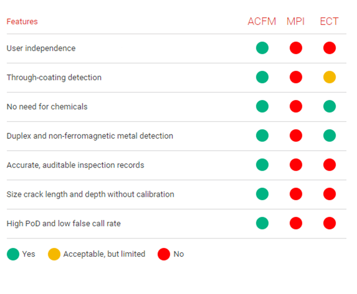
What is the smallest defect detectable with ACFM?
Short Answer
Generally on the range of 2mm (0.07in) long by 0.3mm (0.011in) deep to 10mm (0.34in) long by 1.0mm(0.034in) deep - depending on the material, the surface condition and the probe.
Long Answer
ACFM was developed to reliably detect and size in-service defects with a low number of false calls. It was designed to work on rough or corroded surfaces, or through protective coatings. It was not designed to be an ultra-sensitive detection technique. The results of extensive POD trials carried out over the years have demonstrated that ACFM can reliably detect surface breaking cracks of 10mm long by 1mm deep at manual multi-pass weld toes, or 5mm long by 0.5mm deep on good surfaces. More importantly, however, these same trials have shown that other techniques, while finding some smaller defects, can also miss larger ones. So a better question to ask all of the NDT Techniques, though, is “what is the largest defect that can be missed?” Unlike some techniques the deeper the defect is, the larger the ACFM® signal becomes. ACFM® can be made more sensitive by the use of micro pencil probes and higher frequencies. In this case, defects as small as 2mm (0.866in) long by 0.3mm (0.011in) deep can be detected in ferritic steel (about 4mm (0.157in) by 0.5mm (0.019ins) in non-ferrous metals), but this sensitivity comes at the expense of a higher response to other influencing parameters such as surface roughness or liftoff. The above minimum defect size can thus only be achieved on smooth uncoated surfaces, for example threaded connections.
Can ACFM Detect Sub-Surface Defects or Porosity?
Short Answer
Generally not on ferrous metals, but sub-surface defects can be detected in non-ferrous metals if they are near the surface.
Long Answer
The currents induced in the ACFM® technique are confined to a thin layer at the surface so that only defects lying within this layer can perturb the current and thus be detected. The thickness of the layer (the skin depth) is much smaller for ferritic steel than for non-ferrous metals. The skin depth in ferritic steel is too small to allow the detection of sub surface defects, but the larger skin depth in non-ferrous metals makes it possible to detect defects that do no break the top surface. The signal from a sub-surface anomaly is much less “sharp” than that from a surface breaking defect, so in order to be detected sub-surface defects must perturb a significant portion of the current flow. For this to be the case, a defect must extend to within about half a skin depth of the top surface, and have trough-thickness height of at least half a skin depth. For this reason, standard low frequency probes should be used if sub-surface defect detection is required. The skin depth in low conductivity metals (such as stainless steel, titanium, nickel alloys, bronzes etc.) is around 5-8mm at 5kHz, whereas skin depth in high conductivity metals (such as aluminium, copper and tungsten) is around 1-2mm. The form of the signal from a sub-surface defect depends on the relative sizes of the remaining ligament and the defect length, but usually results in an upward moving Bx (and consequently an upward butterfly loop). Volumetric defects such as corrosion pitting or porosity, give much weaker signals than planar defects, so it is not recommended that ACFM® be used to detect sub surface porosity.
Can ACFM Measure The Through-thickness Depth of An Inclined Crack?
Short Answer
No, it measures crack path length.
Long Answer
The perturbation in the current flow, and hence the size of the ACFM® signal, is related to the extra path length, i.e. the length down the crack face. In ferritic steel, the skin depth is small compared to the crack depth, so no information can be gained on crack inclination. In thick-skin materials, there is an asymmetry in current density either side of an inclined crack which, in principle, could give information on crack inclination (and hence through-thickness depth), but this is very difficult to measure and interpret in practice.
Does ACFM Work on Forgings and Casting?
Short Answer
Yes
Long Answer
ACFM® detects and sizes planar defects in any metal however it is formed. ACFM® is relatively insensitive to surface roughness, so forgings and castings can be inspected as easily as machined or welded components. The main differences to consider are that forgings and castings often have large areas without discrete stress raisers that need to be inspected, for which an array probe would be suited, and also in-service defects can initiate from features such as pores or laps not present in welded or machined components.
Can ACFM Work Through Metallic Coatings, Scale or Rust?
Short Answer
Yes
Long Answer
ACFM® generally has no problem working through rust, surface oxides or other low conductivity layer. ACFM® also works through thin uniform metal coatings such as zinc galvanising, even if the crack does not penetrate the coating. However, some problems can occur with non-uniform metal coatings such as manually applied flame-sprayed aluminium. Such coating produce strong background variations in the signals due to overlapping costs and differences in thickness, which can mask signals from any defects present. In such cases, it is advisable to inspect coated areas away from any anticipated cracks to determine the nature of background variations (if any). The background variations are typically fairly constant over a wide area, so localised signals from a defect can be picked out by comparing adjacent scans (Array Probes would be recommended in this scenario).
Can ACFM Detect Cracks Which Extend The Full Width Across a Plate?
Short Answer
Yes
Long Answer
The usual (and most reliable) method for confirming the presence of a defect is to obtain a complete loop in the butterfly plot, which requires scanning a probe along the complete defect, including passing over both ends. For cracks that run up to an edge, this procedure is modified, so that only half a loop is expected. Obviously if the defect rubs completely across a plate, or full circumference around a pipe, there will be no defect end signals in Bz, and, if the defect is of uniform depth, there will be little change in the Bx signal. In order to detect such defects, the inspection procedure requires a scan across the expected line of the defect. If a defect is present, a sharp dip in the Bx signal will be seen. This transverse scan provides the Bx background and minimum values for sizing purposes. In practice, long fatigue defects, especially at weld toes, normally consist of several cracks which have coalesced together. This process gives rise to local crack bridging and line contacts which give strong ACFM® signals during the normal inspection scan, significantly aiding detection.
Can ACFM Detect Transverse Cracks?
Short Answer
Yes
Long Answer
The directional nature of the input field in ACFM® means that it will not flow across a crack that runs transverse to the scan direction. In practice, an upward going butterfly is often obtained from a transverse defect (due to flux leakage effects), however because this cannot be relied on, the procedure contains an instruction to make a scan with the probe rotated at 90°, in order to detect transverse defects. Once detected, such cracks are sized by scanning the probe along the crack. Detection and sizing of transverse defects is made quicker and simpler with the use of an array probe which contains two energising fields at right angles to each other, so that defects in any orientation are detected in one pass.
Learn more